|
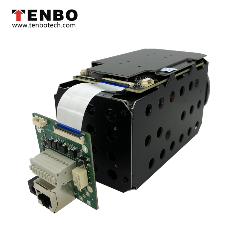
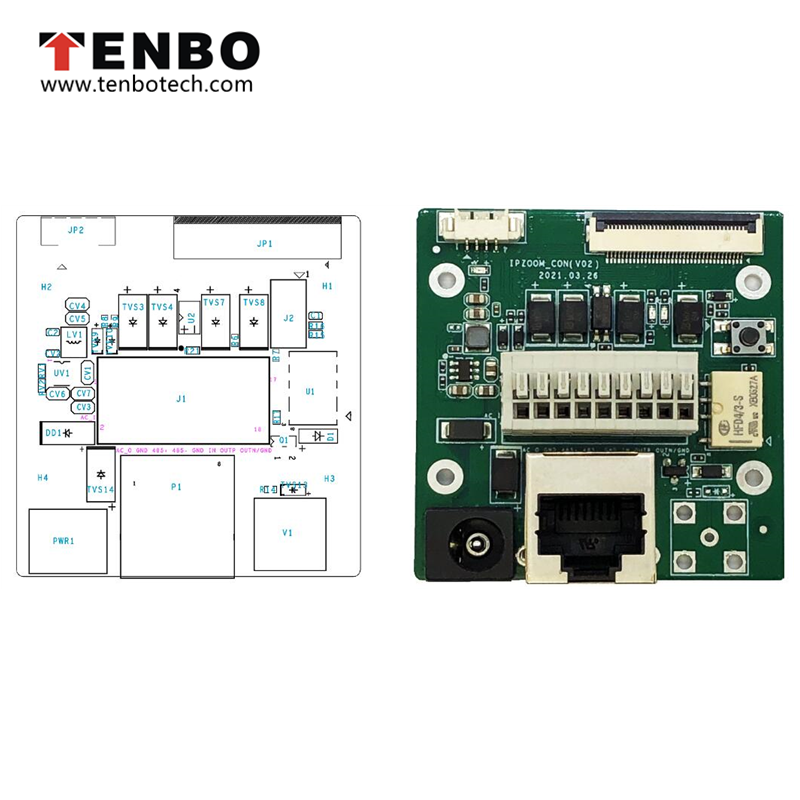
TB-IB301IP Interface Board for HM & DM Series of Block Zoom Camera Modules
|
|
Type |
No. |
Name |
Description |
|
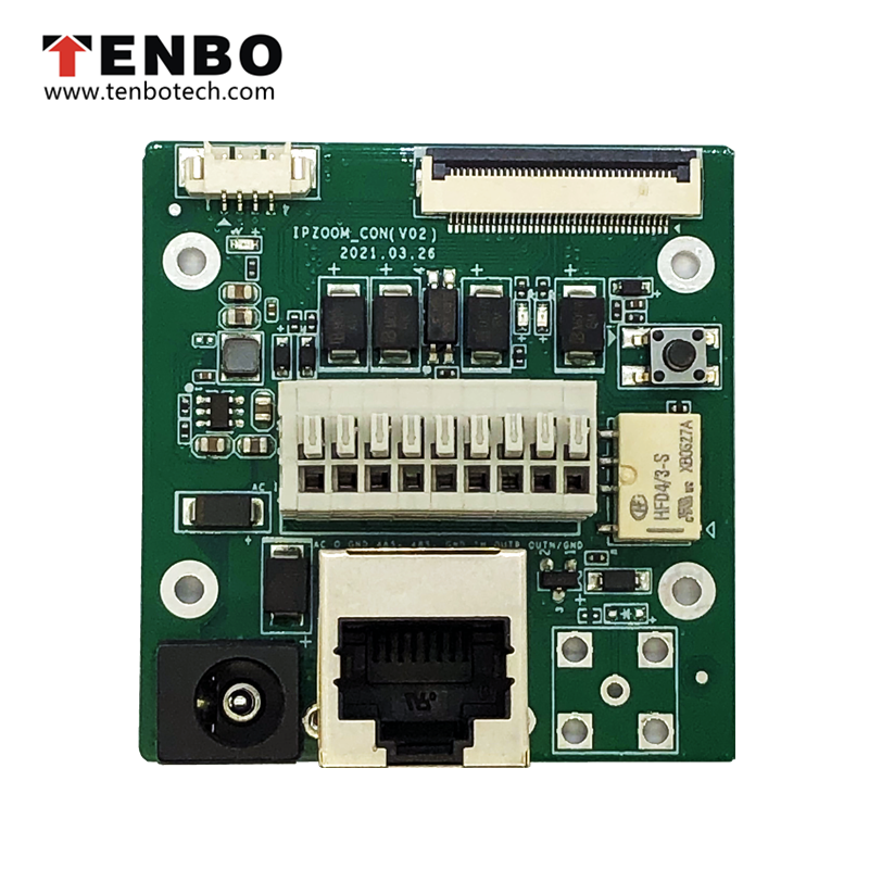
PWR1: Power interface |
|
|
DC12V Power input |
|
J1: Audio and video, alarm input and output, RS485 function port |
1 |
LINEIN |
Audio input signal |
|
2 |
LINEOUT |
Audio output signal |
|
|
3 |
GND |
Power ground |
|
|
4 |
RS -485+ |
RS -485 Line A |
|
|
5 |
RS -485 - |
RS -485 LineB |
|
|
6 |
GND |
Power ground |
|
|
7 |
ALARM_IN |
Electrical level alarm input |
|
|
8 |
ALARM_OUTP |
Level alarm output high (valid) |
|
|
9 |
ALARM OUTN |
Level alarm output low (valid) |
|
|
JP2: UART Port |
1 |
3.3V |
3.3V Power output |
|
2 |
RXD |
UART port, receiving signal (3.3V), using VISCA protocol |
|
|
3 |
TXD |
UART port, sending signal (3.3V), using VISCA protocol |
|
|
4 |
GND |
Power ground |
|
|
P1: RJ45 Ethernet |
1 |
TX+ |
Adaptive network port, physical signal sending (+ differential) |
|
2 |
TX- |
Adaptive network port, physical signal sending (- differential) |
|
|
3 |
RX+ |
Adaptive network port, physical signal receiving (+ differential) |
|
|
4 |
NC |
Empty |
|
|
5 |
NC |
Empty |
|
|
6 |
RX- |
Adaptive network port, physical signal receiving (- differential) |
|
|
7 |
NC |
Empty |
|
|
8 |
NC |
Empty |
|
|
V1: CVBS Coaxial output interface |
|
|
Analog video signal output |
|
JP1: 36Pin for interface board |
1 |
DC12V |
DC12V Power output |
|
2 |
DC12V |
DC12V Power output |
|
|
3 |
DC12V |
DC12V Power output |
|
|
4 |
GND |
Power ground |
|
|
5 |
GND |
Power ground |
|
|
6 |
CVBS |
Analog video output |
|
|
7 |
GND |
Power ground |
|
|
8 |
LINE_OUT |
Audio output |
|
|
9 |
GND |
Power ground |
|
|
10 |
LINE_IN |
Audio input |
|
|
11 |
Empty |
Empty |
|
|
12 |
TPTX+ |
Adaptive network port, physical signal sending (+ differential) |
|
|
13 |
TPTX - |
Adaptive network port, physical signal sending (- differential) |
|
|
14 |
TPRX+ |
Adaptive network port, physical signal receiving (+ differential) |
|
|
15 |
TPRX - |
Adaptive network port, physical signal receiving (- differential) |
|
|
16 |
GND |
Power ground |
|
|
17 |
LINK# |
LINK# indicator |
|
|
18 |
ACT# |
ACT# indicator |
|
|
19 |
ALARM_OUT |
Alarm output |
|
|
20 |
ALARM_IN |
Alarm input |
|
|
21 |
GND |
Power ground |
|
|
22 |
SD_EN |
SDIOcardpowerenable |
|
|
23 |
Empty |
Empty |
|
|
24 |
SD_CD |
SDIO data card detection pin |
|
|
25 |
SD_CLK |
SD Card clock signal |
|
|
26 |
SD_CMD |
SDIO_CMD Card command |
|
|
27 |
SD_DATA3 |
SDIO data bit3 |
|
|
28 |
SD_DATA2 |
SDIO data bit2 |
|
|
29 |
SD_DATA1 |
SDIO data bit1 |
|
|
30 |
SD_DATA0 |
SDIO data bit0 |
|
|
31 |
GND |
Power ground |
|
|
32 |
RS485 - |
RS -485 B Line, using Pelco protocol |
|
|
33 |
RS485+ |
RS -485 A Line,using Pelco protocol |
|
|
34 |
232_TXD |
UART port, sending signal (3.3V) at the module end, using VISCA protocol |
|
|
35 |
232_RXD |
UART port, receiving signal (3.3V) at the module end, using VISCA protocol |
|
|
36 |
SYS_RSET_N |
External key reset signal input |
| Class | Date | Title | Language | Type | Download |
|---|
| Class | Date | Title | Language | Type | Download |
|---|
| Title | Remark | Release notes | Download |
|---|